VW Baywindow Bus - Fuel Injection Vacuum Hoses
by Richard Atwell
(c) Copyright 2003-2011
VW Baywindow Bus - Fuel Injection Vacuum Hosesby Richard Atwell |
|
There doesn't seem to be a comprehensive source for vacuum hose diagrams. Bentley, Haynes and others are sketchy, the parts fiche gif images are grainy and have too much detail and mainly verbal descriptions exist in the Type 2 archives and at Bus Boys. I've compiled this information from personal measurements, ETKA and other sources.
Most images are from my Federal 1978 GE engine. I will document the differences for all models (charcoal canisters, egr, distributors) as I obtain the images and perform some image enhancement to highlight the hoses.
Click on the images to enlarge them.
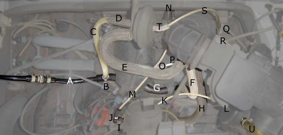
| Label | Description/Location | Type | Inside diameter | Outside diameter | Length | Comments |
|---|---|---|---|---|---|---|
| A | Brake booster | molded hose | n/a | 13mm | n/a | |
| B | Brake booster, air plenum, decel valve | tee | n/a | n/a | n/a | 022 133 083D |
| C | Decel valve to brake booster | hard tubing | n/a | 15mm | 250mm | |
| D | Decel valve to brake booster | hose | 15mm | n/a | 65mm | N 904 023 01 |
| E | Decel valve to intake elbow | molded hose | 19mm | 24.5mm | 370mm | NLA |
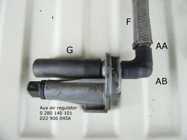
| F | Intake elbow to aux. air regulator | hose | 13mm | n/a | 210mm | N 020 290 3 |
| G | Aux. air regulator to air plenum | hose | 14mm | n/a | 75mm | N 101 238 01 |
| H | Intake boot to oil breather | molded hose | 22mm | 26mm | 350mm | NLA |
| I | Distributor vacuum can | 3 hoses | 5mm | n/a | 35mm | N 020 291 1 |
| J | Distributor vacuum can | tee | n/a | 5mm | n/a | 113 201 943B |
| K | Distributor to air cleaner | plastic hose | n/a | 4mm | 300mm | N 020 139 1 |
| L | Air Cleaner | hose | 5mm | n/a | 35mm | N 020 291 1 |
| M | Distributor to Throttle body | plastic hose | n/a | 4mm | 360mm | N 020 139 1 |
| N | Throttle body | hose | 3.5mm | n/a | 100mm | N 020 291 1 |
| O | Air plenum to pressure regulator | hose | 5mm | n/a | 35mm | N 020 291 1 * |
| P | Air plenum to pressure regulator | plastic hose | n/a | 5mm | 220mm | 867 955 961A |
| Q | Pressure regulator | 3 hoses | 5mm | n/a | 35mm | N 020 291 1 * |
| R | Pressure regulator | tee | n/a | 5mm | n/a | 113 201 943B |
| S | Pressure regulator to decel valve | plastic hose | n/a | 5mm | 310mm | 867 955 961A |
| T | Decel valve | hose | 5mm | n/a | 40mm | N 020 291 1 * |
| U | Air Cleaner to charcoal canister | vinyl hose | 13mm | 16mm | 510mm | N 020 390 1 |
| V | Fuel vapor recovery system | 3 hoses | 7mm | n/a | 50mm | N 020 281 1 |
| W | Fuel vapor recovery system | tee | n/a | 7mm | n/a | 211 201 405A |
| X | Fuel vapor recovery system | metal line | n/a | 7mm | n/a | |
| Y | Tee to charcoal canister | plastic hose | n/a | 7mm | 400mm | |
| Y' | Breather lines to tee | plastic hose | n/a | 7mm | 310mm | |
| Z | Charcoal canister | hose | 7mm | n/a | 60mm | N 020 281 1 |
| AA | Aux. air regulator | metal tube | n/a | 13mm | 30mm | |
| AB | Aux. air regulator | rubber elbow | n/a | n/a | n/a | 022 129 637 |
| Intake runners (4) | hose | n/a | n/a | n/a | 039 133 241 |
All measurements were taken with digital dial calipers rounded for best fit.


General principle: the fan blows air through the canister from the bottom hose. The top hose is how the trapped fumes get blown to the intake. The small breather hose feeds the gastank fumes to the canister.
1980-1983 (mounted in rear passenger wheel well):

1978-1979 (mounted behind battery):

1974-1977 (mounted on firewall):

1972-1973 (mounted before booster fan):
Note: 1972-1977 system which pickup the fan output from the right side tin, use an adapter on top of the fan housing when an a/c compressor is installed.

1970-1971 (mounted above battery):
Note: some 1970 models do not have the charcoal canister. It's likely that only CA models did in this year.
The L-Jetronic system on busses is largely uniform. It was introduced with the 1975 model (Automatic CA 1974 model in small numbers actually starting with VIN 214 2 132 408) and there were major changes half way through 1976 starting with VIN 226 2077 584. These are some of the details.

|
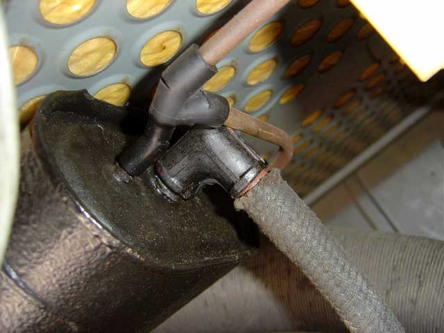
Early models and some 79 models had a dual vacuum dual advance (DVDA) distributor. The retard hose on the back connected to the manifold vacuum system. The advance vacuum connected to the throttle body and EEC valve on the air cleaner same as with the other models. |

|
Instead of a 3-way tee for manifold vacuum, there is a 4-way tee on early FI models. The fourth hose leads to the EGR valve. The manifold port is also relocated to the left side of the plenum just behind the cold start valve. |
|
The early EGR valve has a vacuum hose for activation and an electrical connection which means the early FI system has a special harness in addition to it having a 6-pin AFM plug instead of 7-pin. The electrical connection leads to a microswitch on the throttle body which closes the valve at idle and WOT. |

|
Another difference in the early setup is that the EGR pipe from the EGR valve connects directly to the throttle body instead of the left side of the plenum. This is really hard to reach in this location. |
If you are thinking about swapping a Vanagon engine into your bus (especially if you have carbs) keep in mind that some of the hoses aren't the same length or in the same position. Use this diagram to help make best use of them and to figure out which baywindow hoses you'll still require:

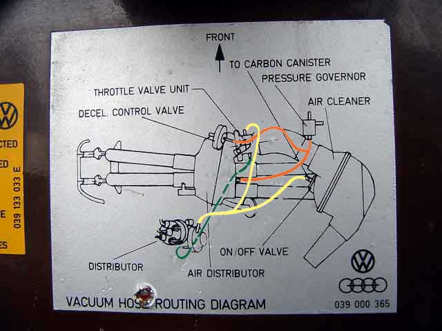
79 CA model (maybe others) had a vacuum diagram on the inside of the engine lid beside the timing instructions. The original diagram sometimes has a print error: the white vacuum hose going to advance side of the distributor is offset. In the second diagram I've colored the lines to show where the hoses connect.
The yellow line is the vacuum advance which connects to the nipple on the advance (right) side of the distributor to the EEC valve on the air cleaner to the backside of the throttle body.
The orange line is vacuum retard that connects the plenum to the fuel pressure regulator to the small nipple on the decel valve.
The green line is a dedicated retard line used only a few FI models: the nipple on the retard (left) side of the dual vacuum can (DVDA) picks up vacuum from the bumper side of the throttle body.
Most FI models have SVDA distributors with only one nipple (advance) like the first photo at the top of this article. This would include 76-78/79Fed models. 75-76.5 and 79 CA models have this DVDA setup shown in the diagram above. Thanks to Andy McKinley for the diagram on the left.

Greg Potts has provided these schematics of the vacuum hose system for early and late models:


02/18/03 - Created
02/23/03 - Added close-up of breather lines showing other plastic line
04/01/03 - Added fuel tank breather lines diagram.
04/12/03 - Added 79 CA Vacuum Hose Routing Diagram
04/22/03 - Added hose information
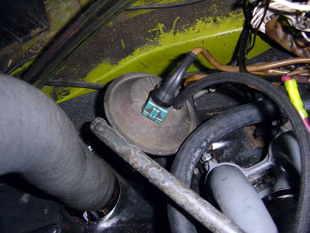
05/06/03 - Fuel Sender info
05/16/03 - Added some references
01/05/04 - Added more hose clamp info
02/08/04 - Added 75 - 76 1/2 differences
02/12/04 - Confirmed ABA clamps fit
02/19/04 - Added breather hose photo behind paint can lid
04/12/04 - Added more 10mm hose measurements
04/14/04 - Added 10mm MB clamp photo and correct part number courtesy of Karl Von Salzen
04/16/04 - Added info about N 020 281 1 to N 020 357 1 breather hoses
05/14/04 - Added accurate fuel line hose lengths
05/31/04 - Added vacuum line schematics
07/21/04 - Added bilge cover photo
07/24/04 - Moved fuel hose information to separate page
09/28/04 - Added 72 charcoal canister photos
05/02/05 - Moved carb hoses to separate article
07/14/05 - Added 79 CA vacuum diagram from Andy McKinley
06/11/07 - Added Vanagon engine layout
07/08/07 - Added some charcoal canister house routing info
09/05/11 - Fixed broken photos, added translate button, updated footer
07/15/19 - Google update: new adsense code, removed defunt translate button
10/20/20 - Added link to Samba forums for vacuum hose diagram collection