VW Baywindow Bus - Temperature Sensor II
by Richard Atwell
(c) Copyright 2003-2020
VW Baywindow Bus - Temperature Sensor IIby Richard Atwell |
|
How do you know if the cylinder head temperature sender (aka Temp Sensor II) in your L-Jetronic FI bus is within spec?
Recently, a rich running condition during warmup had me examining the TS2 in my bus because of the great influence it has on the air fuel ratio as computed by the ECU.
I decided to revisit the testing that I did 17 years ago when I swapped in a new TS2 but rather that recreate the cooktop setup shown previously I decided to see if I could improve the accuracy of the testing, mainly because I was going to test more than a couple of TS2's this time around. I also decided not to use the same measurement equipment I used last time because their accuracy is limited by their price points.
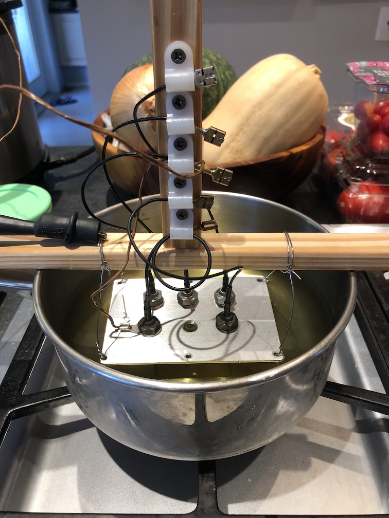
Both the new ohmmeter and thermometer used this time were checked for accuracy against known good test equipment but the biggest change I made was 1) the addition of a heatsink which I drilled and tapped for the sensors and 2) the use of a thermocouple under the sensor.


In addition to better measurement equipment, I undertook these testing improvements to increase the accuracy of the measurements:
A stock washer is under each sensor except for one which has a ring terminal housing the K-type thermocouple and is equivalent for testing purposes.
I also heated the canola up to a maximum (near CHT-ish) temperature at the TS2 mounting location and I let the oil cool back to room temperature to make it easier to control the temperature while I took multiple measurements.
The updated results are surprising and I've preserved the previous results in the article (using strikeout type) to highlight the updated knowledge.
| TS2 | Bosch Date Code | Date of Manufacture | Installed | Mileage |
|---|---|---|---|---|
| Factory sensor | 821 | Jan 1978 | Feb 1978 | TBD |
| Sensor under test | 191 | Nov 2001 | Feb 2003 | TBD |
| NOS TS2 | 389 | Sept 2003 | n/a | n/a |
| NOS TS2 | 684 | April 2006 | n/a | n/a |
| NOS TS2 | 889 | Sept 2008 | n/a | n/a |
| Average (of) NOS sensors | 389, 684, 889 | n/a | n/a | n/a |

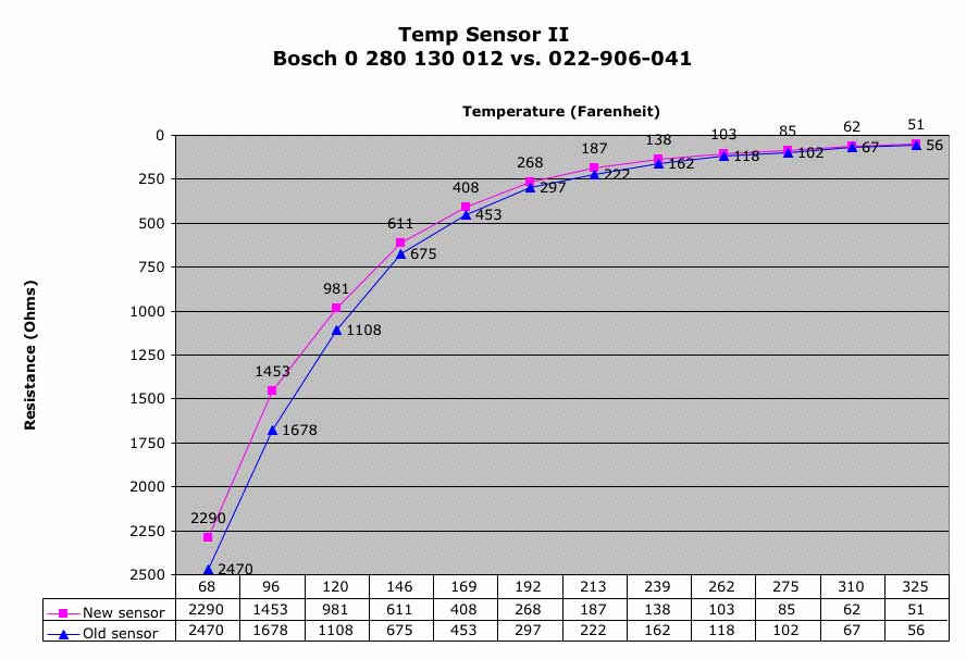
Click on the graph to enlarge. Reading were taken around lower than normal room temperature (62F) but the Fluke 179 has the necessary cold-junction compensation circuitry.
I've averaged the three NOS sensors for future comparisons. I performed multiple passes on these sensors and their resistances values while consistent do vary from sensor to sensor. I don't see the kind of variation in value when compared to the official specs but those numbers might simply be related to the range of values that the ECU can be adjusted against.
Now gone is the more noticeable delta that was originally seen between my factory sensor (821 - Jan 1978) I measured in 2003 and the "at the time" new sensor (191 - Nov 2001) which is now 17 years old with all the accumulated mileage and heating/cooling cy
I attribute the previous delta to 1) uneven heating on the electric stove with the thermometer (still thermocouple based), 2) measuring the oil temperature over rings of the stovetop electric element away from the two sensors sitting above other rings and 3) disturbing the sensors in order to ground them with the ohmmeter.
What's interesting to conclude about the 2020 results is that between all the sensors of various ages, they are essentially producing the same results within a narrow range of values with only minor variations due to manufacturing of the negative temperature coefficient (NTC) sensor inside the housing; even when comparing NOS sensors to aged sensors.
Given this observation, one could conclude that a poor electrical connection is more likely to be the cause of an unwanted high resistance leading to a richer than desired mixture. The mere act of unplugging or changing the sensor can result in a better electrical connection which restores the AFR back to normal.
TS2 test points:
Method: make sure you are getting good readings at all these location before pulling your TS2 and testing against the 2020 graph.
The Bosch L-Jetronic Volkswagen Workshop manual states:
The Vanagon/Type II Fuel Systems ProTraining manual seems a little more precise:
Volkswagen Official Service Manual (Bentley V279 Edition):
Bentley states that the values shouldn't vary by too much although it doesn't explain how much is too much and it appears the value is just the split difference listed in the workshop manual.
Finally, the yellow Workshop Manual (Volkswagen AG):
Jeez! Which one is correct and does it really matter?
Unless the part fails the obvious tests how do you know if it's affecting your mixture? How do you accurately test this part? It would seem to me that the general curve is probably all that you can test within the limits specified in the various manuals for a functioning part. This is a simple component yet seems to cause quite a number of FI busses grief, especially if it is not connected, reads zero ohms (shorted), or too high a value.
With a little stove top science I decided to find out how an old sensor compared to a new one. To do this I poured some canola oil into a pot because it has a high smoke point compared to some other oils. Suspending the bottom of the temp sensors in the oil being careful not to let them touch the bottom, I proceeded to raise the temperature of the oil and monitor it with a digital cooking thermometer. At regular intervals I took temperature readings of both sensors with my ohm meter and graphed the results.
From the graph you can infer that as the sensor ages, the area under the graph decreases. This has the effect of telling the ECU that your engine is actually colder than it really is and it makes the mixture richer than necessary. The other possibility is that the two parts have different curves in the first place. I still have many more TS2 to test before I can draw a conclusion.
Swapping out my own old sensor for a new one, idling during warm-up has become much smoother although the difference in values between the two fall within the published test guidelines. After warm-up, idle is slightly smooth and it has eliminated the hunting in the timing that still lingered even after I switched to an electronic ignition setup (Pertronix). I wouldn't have suspected that after warmup a 10 Ohm drift at 275F could cause the engine to run a little rougher.
The hardest part of testing your sensor is figuring out the ambient temperature. The engine takes a long time to cool down after shutdown so if you take a reading after 3 hours it won't be at the ambient temperature. Touching a cold one with your fingers will raise the temperature also. The best technique is to remove it from the engine, take it indoors, wait overnight then check the air temperature with a thermometer until you get a reading near 68F.

I'd like to graph a known troublemaker and see how it compares. If you have one that doesn't work but meets the specs, please contact me as I'd like to have it.
Click on the graph to enlarge.
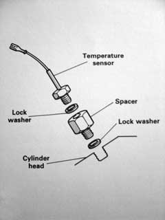
Recently I came across a section in the ProTraining manual that said, "A temperature spacer 022 133 079 is available for cars which run well on initial start-up and when fully warm, but have performance problems only during warm-up. This spacer does not affect the resistance values when the engine is cold or when it is fully warm, but it does delay the change in resistance during warm-up, The spacer temporarily insulates the temperature sensor housing from the heat of the cylinder head".
This is a common problem and I've experienced it myself. When I researched the issue I found no information only stories from other owners with the same issue. It seems many are content to suffer through the warm-up until the bus is at operating temperature when it seems to operate correctly.
You can cure this somewhat by adjusting the idle mixture but what do you do when the bus is warm and the engine is still running too lean when it's warm? You really need this spacer to compensate of the state of the system and to fix the issues during the warm-up cycle BUT it will only cure the problem of a too lean mixture because its purpose is to delay the leaning out of the AFR as the engine warms.
I had always wondered what item #14 was in the fiche alongside the temp sensor (item #41) and it appears to indeed be this spacer.
If you want to make your own spacer, the total length is 25.4mm. The hex portion of the factory spacer is 16.4mm in length and can be made from 13mm carbon steel hex bar stock.
The air-cooled Vanagon CV engine has no such spacer shown in its fiche but the parts diagram for the FI Super Beetle does. Given the mention in the ProTraining manual, I think it's a vital workaround for all aging L-Jet systems and it was a $5 fix that is long lasting.

There is a lot of confusion surrounding the various part numbers for this sender. Only two Bosch parts are available and I don't know how they match to the original VW numbers except by querying the various vintage part catalogs. This is what is stamped on the TS2 installed in my 1978 Westfalia (built February 1978) which has a Bosch date code (821) of January 1978.
| Bosch # | VW # | ETKA |
| 0 280 130 012 | 022 906 041 | 311 906 041A (confusing!) |


There is a Type 4 Workshop Bulletin from 23 Jan 1974 concerning "Backfiring and poor output during engine warming-up". The recommendation is to install a new temp sensor II, 311 906 041A.
It states, "The following list shows which sensors are to be used with what model year. It supplements the information in Workshop Manual K 7.2/1".
| Type 4: Manual and Automatic | Production part | Spare Part |
|---|---|---|
| August 69 - 71 | 311 906 041A | 311 906 041A |
| May 71 | 022 906 041 | 311 906 041A |
| To reduce fuel consumption (only to be paired with control units w/o color sticker) | n/a | 022 906 041A |

From this information I can't see what the exact difference is between these parts but it implies that the 311 part has a higher resistance value than the 022 part and makes the engine think it's colder and injects more fuel. I don't know what the individual Bosch part numbers are and of course new Bosch parts have no VW number stamped on them so it remains a mystery. I took a survey of the parts available for the various models:
| Year | L-Jet Model | Engine Code | VW # | Bosch # | Source |
|---|---|---|---|---|---|
| 1974 | Type 2 (Bus) | AW (1.8L Calif. Automatic) | Possible same as 1975 model | ? | ? |
| 1975 | Type 2 (Bus) | ED (1.8L) | 311 906 041A | 0 280 130 012 | ETKA |
| 1976-77 | Type 2 (Bus) | GD (2.0) | 311 906 041A | 0 280 130 012 | ETKA |
| 1978-1979 | Type 2 (Bus) | GE (2.0) | 311 906 041A | 0 280 130 012 | ETKA |
| 1975-79 | Type 1 (Beetle) | AJ (1.6L) | 311 906 041A | 0 280 130 012 | ETKA |
| 1980-83 | Vanagon | CV (2.0L L-Jet) | 022 906 041A | 0 280 130 012 | ETKA |
I was surprised to find the 022 906 041 part installed in my 1978 engine in the first place because it seems to only have one model year 411 in common with it. It's the only number I can match up to a Bosch replacement part which is listed as an exact replacement in the Type2.com fuel injection cross reference.
Given that there are only two replacement parts available, there is really only one choices: Bosch 0 280 130 012 for (Bus, Bug, Vanagon and 411). What can be concluded from all this mess is that VW and Bosch have superseded both 022 906 041 and 022 906 041A part numbers over the years to 311 906 041A.
Also interesting is the D-Jet parts reference provided by Paul Banders. It in he lists all three known VW part numbers and describes the conflict in the cross reference after doing his research. Included in that list is a a fourth variant of this part:
| Model | VW # | Bosch # |
|---|---|---|
| 1.7L 914 | 311 906 041A | 0 280 130 003 |
He writes:
Discrepancies: The "Porsche Parts Catalog 914 and 914-6 1/1995" lists this Porsche/VW part number for the engines below. The "Bosch Gasoline and Diesel Injection Products, 1998 revision" cross-references this VW part number to the 0 280 130 003 sensor, which is the sensor for the 1968-1969 Type 3's. I checked with my local Bosch supplier and the 003 is the part he found for this Porsche/WV number. The "D-Jetronic Service Manual" from Bosch lists the 0 280 130 012 sensor for these engines and years, but not for the 1974 2.0L. Note that the 0 280 130 003 sensor is used by some 914 owners to get a richer cold engine mixture.
It's reassuring to know that I'm not going crazy but it still doesn't provide a definitive answer on how the resistance varies by part number.
Ronnie at OldVolks.com sent me a VW to Bosch mapping and with Paul's info it seems to largely sort out the confusion although I have no idea how each sensor performs in the bus compared to the stock sensor.
| Model | VW # | Bosch # |
|---|---|---|
| Bus/Type 4 | 022 906 041 | 0 280 130 012 |
| Type 3 | 311 906 041A | 0 280 130 003 |
| ??? | 022 906 041A | 0 280 130 017 |
02/13/03 - Created
02/20/03 - Added Type 4 information
10/19/03 - Added 914/Vanagon info and ProTraining numbers
10/22/03 - Added dizzying array of part numbers
09/05/11 - Fixed broken photos, added translate button, updated footer
07/15/19 - Google update: new adsense code, removed defunt translate button
10/15/20 - Updated with new data and better testing procedure
10/19/20 - Cleanup and formatting